Steps
There are three main steps necessary to complete this project:
Carving The Pumpkin
There really isn't a lot to say here but be creative. When carving though, you will need to make sure that the top half and the bottom half are entirely detached so that the mouth may hinge properly and open and close. I cut out a single square tooth (about 2" long) to act as my hinge. I then held it together by using a small piece of the coat hanger which worked as a nice point of rotation.
For the LEDs I drilled two holes the size of the LED about halfway through the rind. You can then stick the LED leads through the rind to hold the lights in place. I also drilled a small hole in the back of the pumpkin in order to route the rest of the wires through. If you do go with smaller chips and larger pumpkins, you could feasibly make this self-contained.
For the Servo, I held it in place on the bottom of the pumpkin using a couple pieces of the coat hanger. I adjusted its position so that the arm of the Servo was positioned such that when it activated, it lifted the top half of the pumpkin.
Building The Circuit
Since a picture is supposedly worth 1000 words, look here for the circuit connections.
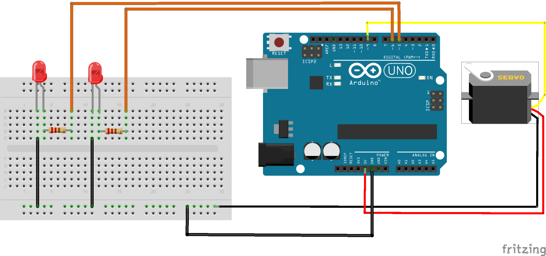 Some points to note in the diagram here:
- The black wires generally represent connection to ground, the red wires represent a connection to power (+5V), and the yellow / orange wires are control wires although they have power running through them as well.
- Resistors - There are a ton of other websites dedicated to this, but we need to have a resistor here to limit the current across the LED to a safe value. Without a resistor, the LED is sure to earn you the Magic Blue Smoke badge
- Another note for the LED, the cathode (-) is typically the shorter leg, the anode (+) is typically the longer leg. If you hook up the polarity backwards, the LED will not light up
- The servo can be a big power drain / spike on the circuit. If the battery power is too low, it can cause the Arduino to reset. Additionally, there are some schools of thought that recommend isolating circuits to prevent damage to the Arduino caused by spikes. While I generally agree that is a good idea, in the interest of simplicity here, it has been omitted.
- You will notice that the control pins for the LEDs and the Servo have a ~ besides them. This indicates that they are a Pulse Width Modulation (PWM) channel. More information can be found here if you are interested in reading more.
Programming The Circuit
The following steps should get you up and running with loading the code onto the controller.
- Install the Arduino Software
- Connect your Arduino to the computer via a USB cable
- In the Arduino UI, will need to make sure that you have the proper Board / Port (under the Tools menu) selected for your configuration
- Load the sketch code (Downloadable from here)
- Upload the code to the board
The code is not overly optimized in an effort to make readability a priority. Similarly, the comments in the code should help to clarify what all it is doing. In the sketch, there are two main sections. The first is the setup() function which is called when the device first powers up to setup variables and initial state. The loop() function is then called indefinitely as long as the device is powered on and the program control is determined from there. In this sketch, the _NextEventTime variable is used to determine when something should happen (either wake up or sleep). When it is time to wake up (~every 2 minutes), the LEDs will fade on to full brightness, then we will randomly choose what the eyes will do (blink, stay on, or light up at a random brightness). The code will then determine if the mouth will start moving or not (set to a threshold of moving 80% of the time). After it is done being active, the mouth will then close and the LEDs will fade out until the next wake period.
Summary
This project just scratches the surface of what you can do with a microcontroller. Some other ideas include motion triggers, sounds, and even some fun stuff you could do with LCD / OLED screens. If you end up tackling this project, would love for you to contact us.